Bare Metal Programming on a Raspberry Pi 2 B
Introduction #
I decided to get my feet wet in embedded last week, in preparation for a certain project that’s on hold, waiting for a shipment.
I’ve had a Raspberry Pi 2 model B v1.1 lying around for many years now. It’s served various more or less pointless purposes in that time, the most useful of which being a LibreELEC media center. The problem is it’s an older model and although the hardware is powerful enough to run Linux, it’s not really powerful enough to run anything meaningful on top.
The ideas I had for it usually revolved around turning it into some kind of household accessory, like a weather or calendar display. I hardly ever see an accurate weather forecast and keeping track of the date doesn’t really take a computer, so I find these applications already quite contrived, but I digress. For those kinds of purposes I find myself deterred by the idea of running the whole of Linux and tinkering with configuration. I guess there’s nothing particularly wrong with that, it’s just not my style.
So last week I figured I would build my own basic kernel for the board and try driving some simple (not) peripherals.
Here’s the repo.
Setup #
I was lucky enough to find an article on OSDev Wiki covering the basic kick-off boilerplate. My setup is almost entirely based on theirs, just cut down somewhat to the bare essentials. Turns out, all it takes to build and boot something on the Pi, aside from the usual C project setup (if there’s such a thing), is:
- a cross-compiler toolchain for 32-bit ARM,
- 3 proprietary firmware files,
- a boot stub written in ARM assembly,
- a linker script.
There are pre-built GNU toolchains for ARM available, that’s nice. Check.
I wrote a simple Makefile inspired by Circle to fetch the firmware files from the firmware repo. Check.
By the way, I had found out about Circle earlier and took a stab at building something in it. I just can’t get any pleasure from dealing with C++. I’m sure the authors have done a great job, it looks to be very comprehensive and it compiled rather painlessly. But I had 10 files open in my editor with in the first 30 minutes of working with the framework and it was kind of throwing my minimalist approach out the window. I wanted to work even closer to the hardware, anyhow, to learn the inner workings.
The boot stub for a basic setup like this only does three things:
- halts/hangs all but one CPU cores, so as to avoid having to deal with synchronization,
- clears the BSS section (static variables),
- jumps to the C entry point.
I can’t write assembly to save my life, but could quickly figure out, with some tedium, what the various instruction blocks do, following the ARM documentation. Check.
My linker script was initially just the start address and the list of sections, but I also had to consider alignment to 32-bit words once I started dealing with more statically allocated/embedded data. But that’s it. Check.
There’s some funky GCC flags in the Makefile to compile for bare metal and link libc with no syscalls.
Blinker #
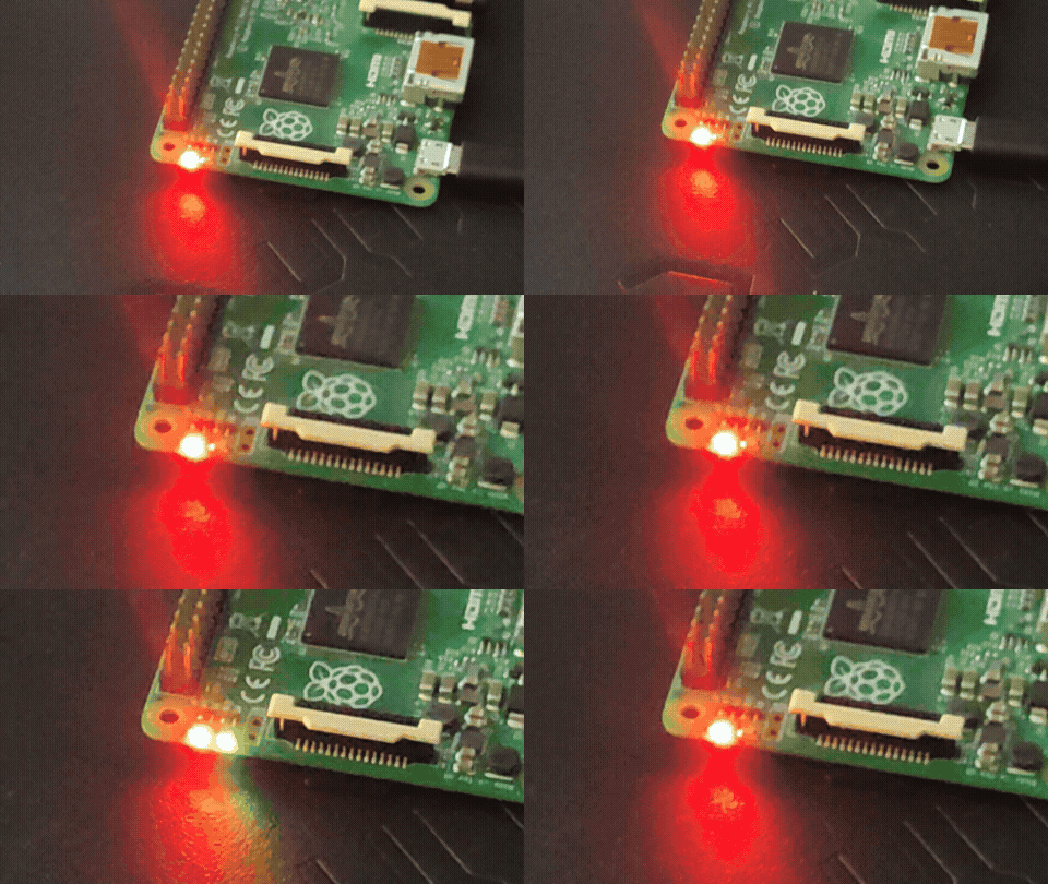
The hello world was to get the ACT LED on the Pi to blink.
Right off the bat, I was sent down what seemed like a wild goose chase trying to find the pin number that the LED is connected to on the board.
The results for “raspberry pi 2 b act led pin number” were entirely useless. If you quote the “act” there is some improvement, but mostly blog and forum posts of people being similarly confused and quoting one another with no real certainty. You can definitely see it specified here and the filename seems to match the chip, but how you’re supposed to get there is beyond me. I was unable to figure this out without resorting to LLMs. This was only the first and least frustrating struggle over the course of this project.
Once I had the pin number, there was still all sorts of weird MMIO address shenanigans to figure out. The BCM2835 ARM Peripherals document uses some weird address offsets, with some rationale based on terminology mostly unfamiliar to me. It turns out you’re supposed to subtract the offset 0x7E000000 that’s used in the document and add 0x3F000000 instead, which is specific to the particular Raspberry Pi model? Again, I can’t confidently point to a definitive source of this information, which is frustrating, but it ended up working in the end.
With all that out of the way, it was relatively easy to continue following the peripheral reference document and program basic GPIO output functionality.
ILI9486 LCD #
The main thing I wanted to get working with the Pi, that I had lying around, was a Waveshare 3.5-inch 320x480 LCD with a Raspberry Pi-compatible shield (GPIO-mounted thing). I heavily underestimated just how much work this would take and how many layers of technical documentation I would need to dig through.
The display has been discontinued now and documentation is poor. From the pinout I was able to gather that:
- the numbering matches that of the Raspberry Pi, namely board pin numbers, not GPIO numbers;
- the LCD pins match the GPIO pins for the
SPI0interface of the Raspberry Pi as documented in the BCM2835 ARM Peripherals reference.
Another piece of info I struggled to find was the name of the controller that the LCD board uses. I still believe this is not in fact documented anywhere, I was suggested ILI9486 by AI initially, and then found it confirmed in some semi-related driver code, I think.
I needed to get or write a driver for SPI, then figure out what to actually send to the LCD board.
I can’t even recall my process here anymore, not chronologically anyway. I’ll just list the things that tripped me up:
- The SPI RX FIFO needs to be cleared periodically, even if only implementing TX. This is in fact stated in the documentation, but I had missed it initially. I believe both RX and TX share the same FIFO under the hood.
- The
DONEbit needs to be explicitly set after a concluded transfer, in addition to clearing the FIFOs, despite it being marked as read-only in the docs. See this linux driver for reference. - The CS (chip select) pin of the ILI9486 needs to be held low across the whole command-data transfer. I ended up driving this pin manually as GPIO output despite it having the documented
SPI0_CE0_Nalternative function. The RS pin is set low for the command byte, then high for the data. - The controller needs to receive a hardware reset pulse before any operation. The pin number is documented on Waveshare’s site, and the reset behavior is documented in the ILI9486 datasheet, but the requirement was not documented in any of the initialization sequences I had found.
- I pieced together the initialization sequence from many different sources. They should all be linked in that file. All of them contain pretty different bytes, so in the end I had to look them up in the datasheet to figure out what they did and then a matter of trial and error to cut it down to the bare essentials, namely:
- configuring the orientation for pixel addressing / memory writing,
- configuring the pixel format itself (later turned out to be forced to RGB666, RGB565 doesn’t work with SPI for whatever reason),
- configuring gamma/voltages (unsure if necessary, but I think the LCD appears dim without this),
- turning on the display.
- All bytes except pixel data sent to the board must be padded with leading
0bytes to 2 bytes / 16 bits. See this function. - RGB666 is sent as 3-byte sequences (no padding to 4 bytes or anything) with 6-bit values shifted left to be the most significant bits. See this function.
Phew!
I later embedded the PSF version of Cozette into the kernel and I’m querying it for glyph pixels to implement super crude bitmap text rendering.
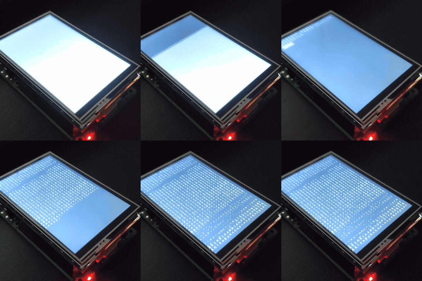
I’ve been assuming polling SPI operation for this. It’s quite slow, CPU-bound I think. Unfortunately implementing the potentially much more performant DMA operation requires a significant increase in complexity, and since I don’t really need high refresh rates, I decided to leave that out for now.
Necessary evil #
The repository also contains code for transmitting bytes over UART. I can’t say I know what’s going on there, since I mostly followed LLM-given instructions for the initialization and data transmission sequences, only consulting the documents for whether the addresses/pins checked out. So I’m not writing about it in detail.
I could not have done all this without the use of LLMs. Technically speaking, I probably could have, but it would have taken me far longer than the extent of my patience and I would likely end up abandoning the project. I would hope this would not be the case for someone more experienced with bare metal / embedded. But for me, having no clear direction for how to progress at several points over the course of the project, resorting to AI made the most sense.
My biggest issue was either the ineffectiveness of the search engines I use or my incompetence in using them. LLMs seem to be at least a decent replacement for those.
That said:
- I had made a commitment not to settle for any addresses, pin numbers, clock frequencies, hardcoded bytes, etc. pulled out of thin air. I tried my best to find and link the source for all of the assumptions the code makes, although it surely isn’t perfect. This also allowed me to gather the several reference documents, which I could later look up more reliably on my own.
- I did not generate any code. It’s unlikely it would have made the whole thing any faster, anyway, since there’s not a lot of it. One thing this makes easier, though, is understanding and keeping track of all the various constants related to MMIO/GPIO/SPI, since I was the one tasked with ensuring consistent naming. How well I did in the end, I’m not sure, I guess it’s a bit of a mess anyway.
In any case, I have found the documentation for bare-metal programming for this particular set of hardware scarce and poor. Linux drivers and configurations, OSes and frameworks made by individuals in the community prove to be the best resources. And an already established framework like Circle is the way to go for all practical purposes.